Phone:
(+971) 56 921 3754
Physical address:
Office #201, Al Quoz Industrial Area
Dubai, United Arab Emirates.
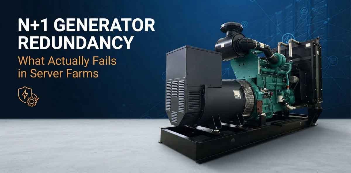
Single Large Generator vs Multi-Unit Synchronization
Reliable power is essential for industrial facilities, construction projects, manufacturing plants, data centres, hospitals, and other operations where an unexpected shutdown can cause serious disruption. In these environments, installing a generator is only part of the solution. Businesses must also consider what happens if the generator fails, requires maintenance, or cannot meet the facility’s full electrical demand.
This is where generator synchronization N+1 redundancy becomes important. By synchronizing multiple generator sets and designing the system with spare generating capacity, businesses can maintain power availability even when one unit becomes unavailable.
For facilities in the UAE, where uninterrupted operations can be critical in demanding industrial and commercial environments, a properly engineered parallel generator system can provide greater operational flexibility, easier maintenance planning, and improved resilience against individual generator failures.
This guide explains how generator synchronization works, how N+1 redundancy differs from a conventional single-generator installation, how automatic load sharing operates, and how Deep Sea Electronics (DSE) 8610 controllers support synchronized generator systems.
What Is Generator Synchronization and N+1 Redundancy?
Generator synchronization is the process of connecting two or more generator sets to a common electrical busbar so they can supply power together. Before a generator joins an energized busbar, its voltage, frequency, phase sequence, and phase angle must meet the system’s synchronization requirements. The generator control system manages this process and permits breaker closure when the required conditions are satisfied.
N+1 redundancy is a capacity-planning method in which the installation has one more generator than is required to meet the specified load. Here, N represents the number of generator sets needed to supply the required demand, while +1 represents the additional set that provides spare capacity.
For example, suppose a facility requires 1,200 kVA of continuous generator capacity. An engineer might consider three 600 kVA generator sets operating in parallel. Two sets can provide the required 1,200 kVA, while the third provides redundancy. If one set fails or needs scheduled servicing, the other two can continue supplying the load, provided their actual available capacity is sufficient.
How an N+1 system works
Generator 1
Online
Generator 2
Online
Generator 3
Redundant set
Common busbar
Synchronized supply and controlled load sharing
Critical facility loads
Industrial equipment, pumps, HVAC and essential services
Illustrative arrangement only. Actual generator sizing, redundancy and load allocation must be verified through an electrical load assessment.
The key point is that redundancy must exist in usable capacity, not just in the number of installed generators. If two remaining generators cannot carry the full facility load after one set trips, the system does not deliver full-load N+1 resilience.
1. The Risk of Relying on a Single Large Generator
A single large generator may appear to be the simplest way to supply an industrial facility. It requires fewer generator sets and can reduce the complexity of synchronization equipment. However, it creates a major operational vulnerability: the entire facility depends on one generating unit.
If that generator trips, the whole plant can lose its generator supply.
What happens when a single generator fails?
Several events can cause a generator to shut down, including:
-
Engine overheating or low lubricating oil pressure.
-
Fuel supply interruption or contaminated fuel.
-
Alternator or excitation-system faults.
-
Electrical overload or short circuit.
-
Protection trips caused by abnormal voltage or frequency.
-
Control-system, starting-system or battery failure.
When a protective trip occurs, the generator breaker may open and disconnect the unit from the facility’s busbar. If there is no independent source capable of taking the load, the facility loses power until an alternative supply becomes available.
For an industrial plant, the consequences may include interrupted production, stalled machinery, stopped pumps, loss of cooling, process interruptions, and equipment restarting delays. Facilities with sensitive equipment may also require controlled recovery procedures before operations can resume.
A standby generator or an automatic transfer arrangement can mitigate this risk, but it must be designed, rated and configured to take over the required loads. Merely having another generator somewhere on site does not guarantee an uninterrupted transfer.
Why N+1 redundancy reduces this risk
A correctly designed parallel system distributes the required generating capacity across several sets. If one unit becomes unavailable, the remaining sets can continue to feed the busbar if enough capacity is available and the control and protection systems respond correctly.
This is particularly relevant to industrial facilities that cannot afford to depend on one engine, one alternator, or one generator breaker for their entire power supply.
For businesses assessing their requirements, industrial generator rental can be a starting point for exploring industrial power capacity. The correct arrangement will depend on the facility’s load, required redundancy, operating schedule and site conditions.
2. Single Large Genset vs Parallel Generator System: Which Is Better?
The choice between one large generator and several synchronized sets depends on more than total kVA capacity. Engineers must consider what happens during a failure, how the plant operates at partial load, whether maintenance can be performed without interrupting production, and the cost of the complete installation.
The following comparison outlines the principal differences.
| Factor | Single large generator | Paralleled N+1 system |
|---|---|---|
| Initial equipment | Usually fewer generator sets | Multiple generator sets plus synchronization and control equipment |
| Failure of one set | Can interrupt the entire generator supply | Remaining sets can carry the load if adequate N+1 capacity is available |
| Scheduled maintenance | Requires a shutdown, another supply or a separate standby arrangement | One set can be isolated while the others remain online, subject to capacity |
| Load variation | One unit must accommodate changing demand | Sets can be started and stopped according to demand |
| Future capacity expansion | May require replacement or an additional independent system | Additional compatible sets may be integrated if the system is designed for expansion |
| Control complexity | Generally simpler | Requires coordinated synchronization, protection and load sharing |
| Partial-load operation | May operate at low load during periods of reduced demand | The number of running sets can be adjusted to suit demand |
| Equipment footprint | Often fewer individual units | More units and potentially more space for panels and service access |
| Maintenance flexibility | Limited without alternative supply | Greater flexibility through planned rotation of sets |
| Capital and installation cost | Often lower for a simple installation | Usually higher due to additional equipment and controls |
This comparison is consistent with the technical considerations described in Terex Diesel’s generator-paralleling guide.
Example: Comparing two system designs
Consider a facility with a required load of 1,200 kVA.
Option A: One 1,400 kVA generator
A single 1,400 kVA set has sufficient nominal capacity for the example load, assuming suitable site derating and operating margins. However, if that unit trips or is taken offline for maintenance, its generating capacity becomes unavailable. The facility needs another independent supply or must accept an interruption.
Option B: Three 600 kVA generators in an N+1 arrangement
Two 600 kVA sets provide 1,200 kVA of nominal combined capacity, while the third set provides redundancy. If one set becomes unavailable, the two remaining sets can still meet the example load at their rated combined capacity, provided derating, power factor, transient loads, auxiliaries and operating margins have been accounted for.
This is an illustrative sizing example, not a final equipment specification. A real design must establish whether the required capacity is expressed in kW or kVA and verify the load profile, starting currents, site conditions and the applicable generator ratings.
The important distinction in the single large genset vs parallel decision is therefore not simply how much power the system can produce when everything is working. It is how much usable power remains when a generator is unavailable.
3. How Generator Synchronization Works
Before multiple generators can operate in parallel, their electrical outputs must be synchronized. Connecting generators without meeting the required synchronization conditions can create severe electrical and mechanical stresses.
A synchronization controller measures the incoming generator’s electrical parameters against those of the live busbar. It then adjusts the engine speed and alternator voltage, as supported by the system design, to bring the incoming generator into the permitted synchronization window.
The essential conditions are:
Voltage matching: The incoming generator’s voltage must be sufficiently close to busbar voltage. Significant differences can cause unwanted reactive currents.
Frequency matching: The incoming generator’s frequency must be close to the busbar frequency. A mismatch can create large transient currents and torque disturbances.
Phase sequence: The phase order must match the existing electrical system.
Phase-angle matching: The incoming voltage waveform must be sufficiently aligned with the busbar waveform at the moment of connection.
Once the configured conditions are met, the synchronization controller can command the generator breaker to close. The generators can then share the connected load according to their control configuration.
The precise acceptance windows are determined by the generator equipment, controller settings, protection scheme and applicable engineering requirements. They should not be treated as universal fixed values. Reference: Terex Diesel, Paralleling (Synchronising) Generators.
Why the synchronization panel matters
The synchronization panel coordinates the generator breakers and control signals needed to connect the sets safely. A properly engineered system also includes protective functions, interlocks and a defined response to faults or controller communication failures.
For N+1 redundancy, the panel and associated controls must do more than connect generators. They must support the intended failure response, including bringing available reserve capacity online when necessary, removing faulty equipment from service, and preventing unsafe breaker operations.
These functions should be verified during commissioning through appropriate testing rather than assumed from the presence of synchronization hardware alone.
4. Deep Sea Electronics DSE 8610: Load Sharing and Synchronization Logic
The Deep Sea Electronics DSE 8610 is a synchronizing and load-sharing control module designed for multi-generator applications. The manufacturer’s documentation describes its ability to synchronize up to 32 generators, monitor operating conditions and faults, and automatically start or stop generator sets in response to load demand or fault conditions. Official DSE 8610 product documentation.
For facilities implementing a parallel generator system in the UAE, the controller can form part of the automation architecture that coordinates multiple generator sets. The complete solution still depends on compatible engine governors, alternator voltage regulators, circuit breakers, current and voltage sensing, communication links, and correctly configured protection settings.
How the DSE 8610 coordinates generator operation
A typical operating sequence involves the following stages.
1. Start request
The system requests a generator start because of a load requirement, an operating schedule or a configured control input.
2. Electrical checks
The controller monitors generator and busbar measurements and checks whether the incoming set is ready for synchronization.
3. Synchronization and breaker closure
When the configured conditions are satisfied, the controller coordinates the connection of the generator to the live busbar.
4. Load sharing
The configured load-sharing method coordinates the generators’ contributions while their protection and operating limits remain in effect.
5. Monitoring and response
The system monitors operating status and configured fault conditions. Depending on the design, it can initiate alarms, isolate a faulty set and request reserve capacity.
This sequence is a simplified explanation of a typical installation, not a universal controller configuration. Exact start priorities, breaker logic, load thresholds and fault responses must be established during system design and commissioning.
Why the DSE 8610 is relevant to N+1 redundancy
A redundant generator is useful only if it can be started, synchronized and connected when required. Load-demand logic helps coordinate the available sets as the facility’s demand changes.
For example, if a facility has three generators and two are normally sufficient for the current demand, the control strategy can retain the third set as reserve capacity. If the load rises, or an operating set becomes unavailable, the configured sequence can bring the reserve set online.
The DSE 8610 MKII product documentation also identifies features such as a multi-set communication link, optional communication redundancy, integrated governor and automatic voltage regulator control, and configurable monitoring and protection functions. These capabilities can support a carefully engineered redundant installation, although the overall system’s reliability also depends on its other components. Source: DSE 8610 MKII manufacturer specifications.
5. Droop Control vs Isochronous Load Sharing
One of the most important aspects of generator synchronization is controlling how much real and reactive power each generator supplies after the sets are connected in parallel.
Two terms are particularly important:
-
Active power (kW): The useful real power delivered to electrical loads.
-
Reactive power (kVAr): Power that supports the magnetic fields required by many inductive electrical loads, including motors and transformers.
Generator controllers coordinate these contributions through the engine governor and alternator voltage regulator. Droop control and isochronous load sharing are two approaches to managing this process.
What is droop control?
Droop control allows a generator’s operating frequency to decrease slightly as its active-power output increases. This relationship helps parallel generators share the load without requiring every unit to maintain exactly the same frequency through a central isochronous control loop.
In simplified terms, a generator with a configured frequency-droop characteristic responds to increasing load by adjusting its engine fuel input and operating speed according to the droop curve. When compatible generators operate together, their governor characteristics help establish how the total active load is divided.
Voltage droop works on a similar principle for reactive power. The alternator’s voltage regulation responds to reactive loading, helping the generators share kVAr demand.
Droop settings must be coordinated across the participating generators. Poorly matched settings can cause unequal load distribution, circulating reactive currents or operation outside the intended limits.
Droop control vs isochronous control
| Feature | Droop control | Isochronous load sharing |
|---|---|---|
| Frequency response | Frequency changes slightly with load according to the droop setting | The control system aims to maintain nominal frequency while sharing active load |
| Coordination | Can support sharing between compatible governor systems using appropriate droop characteristics | Commonly uses communication between compatible controllers |
| Active power distribution | Influenced by governor droop characteristics and generator ratings | Controlled according to the configured sharing strategy and generator ratings |
| Typical application | Systems requiring droop-based sharing or compatible control arrangements | Multi-generator systems using coordinated electronic load sharing |
| Configuration considerations | Droop curves and governor settings must be coordinated | Communication, controller configuration and governor interfaces must be correctly engineered |
The DSE 8610 documentation distinguishes between droop-based sharing and isochronous kW sharing using the multi-set communication link. The controller’s available operating modes and exact behaviour depend on the model, configuration and overall system arrangement.
How DSE 8610 load sharing works in practice
In a compatible isochronous arrangement, the controllers coordinate active-power sharing so that generators contribute according to the configured sharing strategy while the system maintains nominal frequency.
In a droop-based arrangement, the participating governors use their configured droop characteristics to establish load sharing. Depending on the application, the DSE controller can be configured for droop-based operation, isochronous sharing or a suitable combination of modes.
Reactive power sharing is a separate but equally important consideration. Alternator automatic voltage regulators (AVRs) must be coordinated so that generators contribute reactive power appropriately and avoid excessive circulating currents.
For an N+1 installation, correct load sharing helps ensure that the remaining generators do not become overloaded when the system loses one unit. Engineers should verify the active and reactive load-sharing behaviour under normal conditions and during simulated generator loss.
6. Rolling Maintenance: Servicing a Generator Without Power Downtime
One of the main operational advantages of a correctly designed N+1 system is the ability to carry out maintenance on one generator while the other units continue to supply the facility.
This is commonly described as rolling maintenance: taking generator sets out of service one at a time, according to a planned maintenance schedule, without interrupting the required electrical supply.
A practical maintenance example
Consider a facility with three 600 kVA generator sets in an N+1 arrangement and a required load of 1,000 kVA.
During normal operation, two sets can provide 1,200 kVA of nominal combined capacity, leaving the third available as reserve. If the operating plan allows, the sets can be rotated so that each generator receives periodic maintenance.
A typical maintenance sequence is:
-
Confirm available capacity. Verify that the remaining generators can safely carry the actual load, including operating margins and any site derating.
-
Check the reserve arrangement. Confirm that the standby set, if required by the maintenance plan, is available and that the system has sufficient capacity following the planned isolation.
-
Transfer the load if needed. Synchronize and connect another set before unloading the generator scheduled for maintenance, following the approved operating procedure.
-
Unload and isolate the selected generator. Follow the approved breaker, shutdown, isolation and lockout/tagout procedures.
-
Perform the scheduled work. Carry out the required inspections, servicing, repairs and testing while the unit is safely isolated.
-
Return the generator to service. Complete inspections and operational checks, then synchronize and reconnect the generator in accordance with the commissioning and operating procedures.
This sequence is illustrative. The exact procedure must be established by qualified personnel for the particular switchgear, control system and facility.
What must be checked before removing a set?
Rolling maintenance does not automatically guarantee uninterrupted power. The operating team must confirm that:
-
The remaining generators have sufficient continuous and transient capacity.
-
The facility’s critical loads can tolerate the proposed operating arrangement.
-
The control system can manage the changed generator availability.
-
The busbar, breakers and protective devices can safely support the operating configuration.
-
Fuel, ventilation, cooling, exhaust and auxiliary systems remain suitable for the revised arrangement.
-
Maintenance isolation will not compromise shared equipment or common control components.
A further distinction is important: if a facility has only the minimum number of generators required to meet its load, taking one unit offline for maintenance may eliminate its N+1 reserve. Maintaining both the required load and a spare set throughout maintenance requires sufficient additional installed capacity or another engineered source of backup power.
Why rolling maintenance is valuable for industrial operations
Planned maintenance can help reduce the risk of unexpected failures, support more consistent operating availability and make maintenance scheduling more flexible. Rather than shutting down the entire generating plant to service one unit, the operator can rotate equipment through planned service intervals.
For facilities that need temporary capacity during maintenance, commissioning, plant expansion or an equipment replacement project, rental power plant solutions may also be worth evaluating as part of the continuity plan.
The rental configuration should be assessed for capacity, synchronization compatibility, switchgear requirements, site access, fuel arrangements and the time needed to install and commission the equipment.
7. What Happens When One Generator Trips in an N+1 System?
The response to a generator trip is a critical test of whether an N+1 system delivers the intended resilience.
Suppose three generators are operating in parallel, and one suddenly trips because of an engine fault. The generator’s protection system should respond to the fault, and its breaker should isolate the unit as required by the protection design. The remaining generators must then respond to the changed electrical load.
Depending on the system configuration, the response may include:
-
Detecting the loss of a generator and its contribution to the busbar.
-
Redistributing the active and reactive load among the remaining generators.
-
Starting and synchronizing a standby generator if additional capacity is needed.
-
Initiating alarms so operators can investigate the fault.
-
Disconnecting non-essential loads if the remaining available capacity is insufficient.
A properly engineered N+1 system aims to maintain the required critical load following the loss of one generator. However, the result depends on the available capacity, load dynamics, protective coordination, controller configuration and the performance of the remaining equipment.
For example, a facility drawing 1,000 kVA from two operating 600 kVA generators may have enough remaining capacity if one generator trips and a third 600 kVA set is available and can be connected within the facility’s ride-through requirements. The actual response must account for the transition period, the nature of the loads and the generator’s ability to accept the additional demand.
N+1 redundancy is not the same as zero interruption under every failure scenario. A generator trip may cause a short transient or voltage and frequency disturbance even if the system successfully restores its supply. Loads that cannot tolerate such disturbances may require additional measures, such as UPS systems, energy storage or other independent power arrangements.
Engineers should therefore test generator-loss scenarios during commissioning, including the loss of the largest operating unit and the system’s response to reserve-generator starting delays.
8. Designing a Parallel Generator System in the UAE
A parallel generator installation requires careful planning beyond selecting the combined generator rating. UAE facilities may operate in demanding ambient conditions and may have substantial cooling, pumping, motor-starting or industrial process loads. The design should reflect the actual site and application.
The following considerations are particularly important.
Accurate load assessment: Determine the continuous kW and kVA requirements, power factor, starting currents, load steps and critical-load priorities. Do not size the installation using connected load alone without evaluating the expected demand.
Environmental derating: Check the generator manufacturer’s ratings for the installation’s ambient temperature, altitude, ventilation and cooling conditions. Nominal nameplate capacity may not equal usable site capacity.
Synchronization and protection: Specify suitable synchronizing controllers, switchgear, circuit breakers, busbars, protection settings and interlocks. Confirm compatibility across all generator sets and their control equipment.
Load sharing: Establish how the generators will share active and reactive power. Verify governor and AVR compatibility and configure the controllers for the selected operating mode.
Redundancy verification: Calculate the capacity available after the loss or planned isolation of the largest relevant generating unit. Include suitable operating margins and confirm that the remaining units can support the required loads.
Maintenance and monitoring: Establish a planned maintenance schedule, fault-response procedures, alarm monitoring and a process for testing the standby capacity.
Future expansion: If demand is likely to increase, assess whether the synchronization panel, switchgear, protection systems and generator controls can accommodate additional sets.
These considerations should be addressed during the engineering design, procurement and commissioning stages, rather than after the generators have been installed.
9. When Should a Business Choose N+1 Generator Redundancy?
An N+1 arrangement is worth considering when the cost and consequences of a power interruption are greater than the additional investment and complexity of a redundant installation.
Typical applications include:
-
Manufacturing plants where a shutdown disrupts production.
-
Data centres and server facilities requiring carefully managed power continuity.
-
Hospitals and essential-service buildings with critical electrical loads.
-
Commercial buildings with significant cooling and pumping requirements.
-
Construction projects where a generator failure could delay work.
-
Industrial facilities that need to maintain operations during scheduled generator servicing.
A single large generator can remain a suitable option for facilities with less demanding continuity requirements, a dependable alternative power source or a lower tolerance for the cost and complexity of parallel operation.
The decision should be based on a risk assessment and a comparison of the total installed cost, maintenance requirements, fuel consumption, expected availability and consequences of downtime.
10. Frequently Asked Questions
What does N+1 mean in generator synchronization?
N+1 means the generating system has enough capacity to meet the required load with one additional generator beyond the number needed for normal operation. If one unit fails or is removed for maintenance, the remaining available capacity should still meet the specified demand, subject to the system design and operating conditions.
Can generators of different sizes operate in parallel?
Yes, generators of different ratings can operate in parallel if their electrical characteristics, control systems, protection arrangements and load-sharing methods are compatible. Their contributions must be coordinated appropriately, and the total available capacity must be calculated using the actual ratings and site conditions.
What is the difference between droop control and isochronous load sharing?
Droop control uses a defined relationship between load and frequency or voltage to help generators share power. Isochronous load sharing coordinates active-power output to maintain nominal frequency while distributing the load. The appropriate approach depends on the controller configuration, governor and AVR capabilities, and system architecture.
What does the DSE 8610 do in a parallel generator system?
The DSE 8610 is a synchronizing and load-sharing controller that monitors generator operation and supports coordinated generator connection and control. The DSE 8610 MKII is designed for multi-generator systems and supports synchronization of up to 32 generators. Its actual functions depend on the selected configuration and associated equipment. Official manufacturer documentation.
Can N+1 redundancy eliminate downtime during maintenance?
It can allow one generator to be serviced while the other units continue supplying the load, provided sufficient capacity remains and the maintenance procedure is correctly planned. It does not guarantee uninterrupted power during every fault or transfer event. Sensitive loads may require additional backup systems.
Is a parallel generator system more expensive than a single genset?
A parallel system generally requires additional generator sets, synchronization equipment, switchgear, controls and engineering. However, it may provide greater maintenance flexibility and reduce the operational exposure associated with a single-generator failure. The financial comparison should include the potential cost of downtime as well as the initial installation cost.
How many generators are needed for N+1 redundancy?
The number depends on the facility’s load and the capacity of each set. For example, three 600 kVA sets can provide an N+1 arrangement for a 1,200 kVA nominal load because two sets meet the stated requirement and one additional set provides redundancy. Actual sizing must account for derating, power factor, load steps and the specified operating margin.
Conclusion
Generator synchronization and N+1 redundancy provide a practical approach to improving power resilience in industrial and commercial facilities. By operating compatible generators in parallel, coordinating their load contributions and retaining sufficient spare capacity, businesses can reduce their dependence on a single generating unit.
The benefits extend beyond backup capacity. A well-designed system can support rolling maintenance, accommodate changing demand, provide more flexible operating arrangements and simplify future capacity planning. However, these benefits depend on accurate load calculations, compatible equipment, correct controller settings and proper commissioning.
Deep Sea Electronics’ DSE 8610 controller provides synchronization, monitoring and load-sharing capabilities that can form part of such an installation. Droop and isochronous control offer different ways of coordinating generator output, and the appropriate configuration should be selected for the specific system.
For businesses planning a new installation, upgrading an existing power system or arranging temporary industrial power, explore industrial generator rental and rental power plant solutions to assess suitable options for the project’s capacity and continuity requirements.
Need Reliable Temporary Power or Cooling in the UAE?
From 20 kVA mobile silent generators up to multi-megawatt synchronized power plants and 500 TR packaged chillers. Complete turnkey delivery, cabling, and 24/7 on-site maintenance across Dubai, Abu Dhabi, and Sharjah.